Description
Calibration Values Provided and Ready to Input into Mission Planner
Having accurate calibration values to input into ArduPilot is of paramount importance for the proper computation of battery consumption. This is improves the accuracy of the battery indication in FlightDeck and Mission Planner. It also improves alerting and failsafe flight mode activation, which are very important safety features.
Not everybody will go through the steps of properly calibrating their power module. MAUCH provides individual highly accurate calibration values for each current sensor in a format that is ready for Mission Planner.
1. On the mission planner’s INITIAL SETUP | Optional Hardware | Battery Monitor screen set the “Sensor” to “Other”.
2. Enter the voltage divider from the final test result and press “TAB” or click out of the field. Then the “calculated battery voltage” should be within a few millivolt of the actual battery voltage.
3. Enter the “Amperes per volt” from the final test result (A/V) and press “TAB” or click out of the field.

Why use a Hall sensor ?
- Better Accuracy The measurement over a normal shunt resistor is not accurate at lower currents (<3.0A). For a Hall sensor the measurement starts at 0.5A with an accuracy of /-0.5A over the whole range up to 200A! This means better battery consumption calculations and ultimately more flight time.
- More Efficient A shunt resistor creates heat due to the voltage drop, the Hall sensor has only an internal resistance of 100uOhm, so there is no power loss.
- Linear Measurements Due to the heat created by a shunt resistor and the power cable, the measurement of the current is not linear and depends on the temperature.This doesn’t happen to a Hall sensor, a temperature change (created by the main LiPo cable) will not influence the measurement.
- Higher Currents The current flows only through the Hall sensor and NOT through the PCB. Most other current measurement boards have the main cable soldered to the PCB and then it goes to the shunt resistor -> these boards can’t handle over 60A constant current !
Why do only a few supplier use true Hall sensors for current measurement for unmanned vehicles?
- Hall sensors are very expensive compared to normal shunt resistors and not everybody out there wants to spend the money to top up for a good measurement system. So the sales quantity and profit will not be within the target.
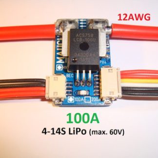
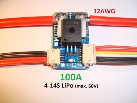
What is the maximum continuous current and what is the over-current of the sensor board ?
- The sensors boards are capable of continuous current of 100A for HS-100-XX and 200A for HS-200-XX for an unlimited amount of time.
- The maximum over-current is 1 second for 1200A@25°C and 800A@85°C.
Why sensor board and UBEC are separated ?
- A switching power supply can be a very “noisy” part in the power supply chain and it is very difficult to shield the coils (1.5MHz) from the current measurement board. So it was decided to keep the two away from each other.
Advantage compared to other power modules for Pixhawk flight controllers
- The voltage sensor has a filter which reduces the risk of false RTL trigger, which might happen in very windy conditions due to sudden motor speed up to keep the flight leveled.
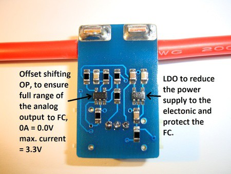
- Even “if” something went wrong with the current board, the flight controller’s analog input is protected as the maximum output voltage of the sensor board is 3,7V limited by the OP.
- Thanks to the offset shifting, the current measurement uses the full analog input range of the flight controller from 0.0V (0A) until 3.3V (100A / 200A), so there is no need to adjust parameter “BATT_AMP_OFFSET”. Due to the full range of the current measurement, the display on FlightDeck or MP is more stable.
- Most Attoboards, or even the original 3DR power module, have the problem with sudden voltage drops during hover (0.5-1.5V) which are caused by the resistance of the installed connectors and main battery wires.
- In these sensor boards the voltage drop measurement error is minimized as it only measures the resistance of the positive main wire.
- The error can be further reduced by connecting the BEC as close as possible to the battery connector.
The total current of two LiPos can be measured using a second sensor and a sensor hub.

Two 4S-14S LiPos with Pixhawk

Two 4S-14S LiPos with Pixhawk 2.1
To set up a system with two Mauch Hall Effect Current Sensor for a configuration with two LiPos you would need:
2x Current sensor board:
HS-100-LV or HV = 2x100A = 0-200A Total
HS-200-LV or HV = 2x200A = 0-400A Total
1x 2-6S BEC or 4-16S HYB-BEC
Quality Control
The final QC before the boards are shipped, is a setup with an FC (Pixhawk) and connected to Mission Planner to check the calibration values for current and voltage measurement.
This final test result is passed to the customer. Which power module supplier out there actually use the PM to power up a real FC before shipment ?